A Digital Security Door Lock System with RFID: Enhancing Student Card (KTM) Capability for Door Unlock and Attendance Electrical Laboratorium based on IoT using NodeMCu 8266
Penelitian ini bertujuan untuk meningkatkan sistem keamanan suatu ruangan menggunakan RFID dan NodeMCu ESP8266 berbasis Internet of Thing’s sebagai media pengumpulan informasi yang dapat merekam jejak pengguna Laboratorium Teknik Elektro dengan memaksimalkan Kartu Tanda Mahasiswa sebagai akses masuk dan keluar. Sistem yang dirancang terdiri dari control circuit yang mengendalikan buka tutup pintu dengan dua lapis keamanan yaitu RFID dan Password, localhost web yang memantau, menampilkan dan merekam informasi status pengguna seperti membaca nomor kartu pengguna, nama, waktu masuk atau keluar, sehingga dapat meminimalisir kehilangan aset berharga didalam Laboratorium Teknik Elektro. Data informasi yang direkam terbagi menjadi 2 tempat penyimpan: 1). Google Spreadsheet sebagai 3rd platform IoT Clouds MQTT 2). Localhost xampp yang berada di PC Server.
Kata kunci :
Radio Frequency Identification, NodeMCu ESP8266, Internet of Thing’s, Google Spreadsheet, IoT Cloud MQTT, Localhost xampp.
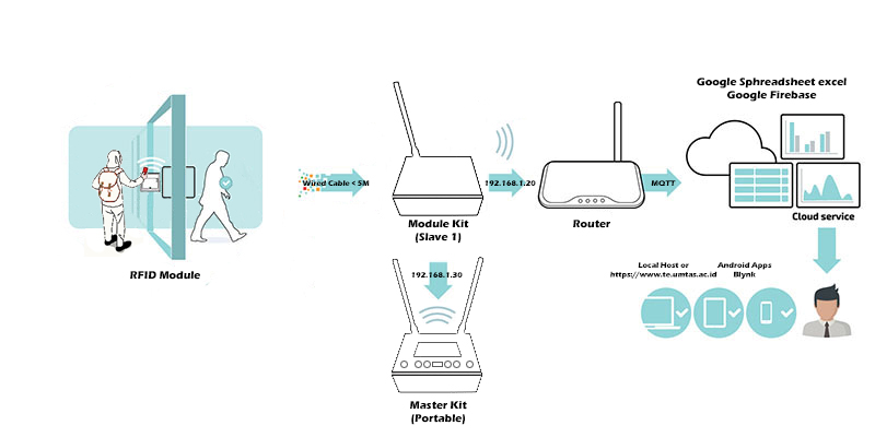
0. Illustration
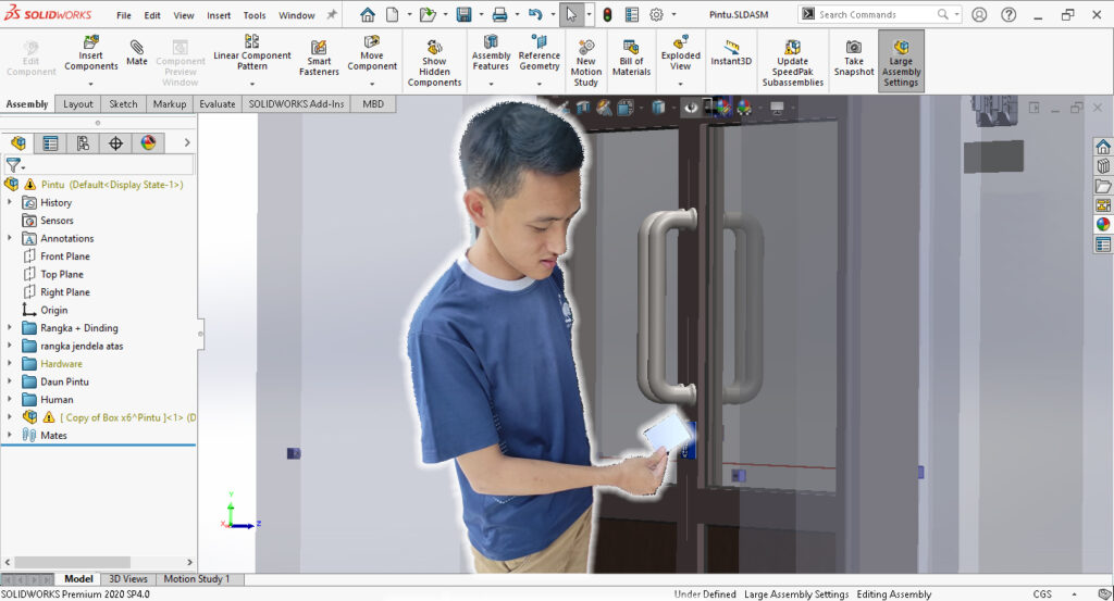
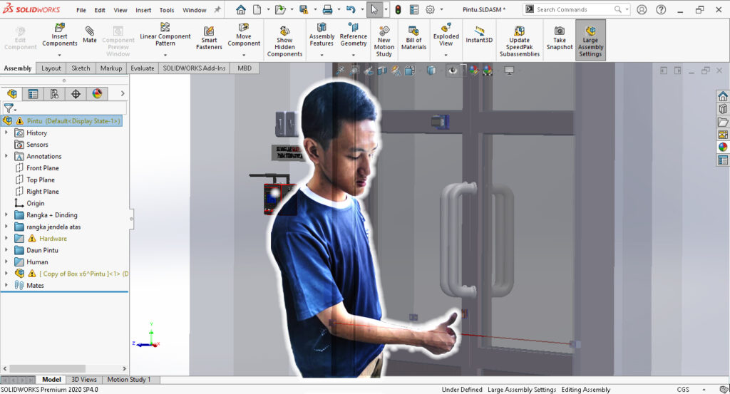
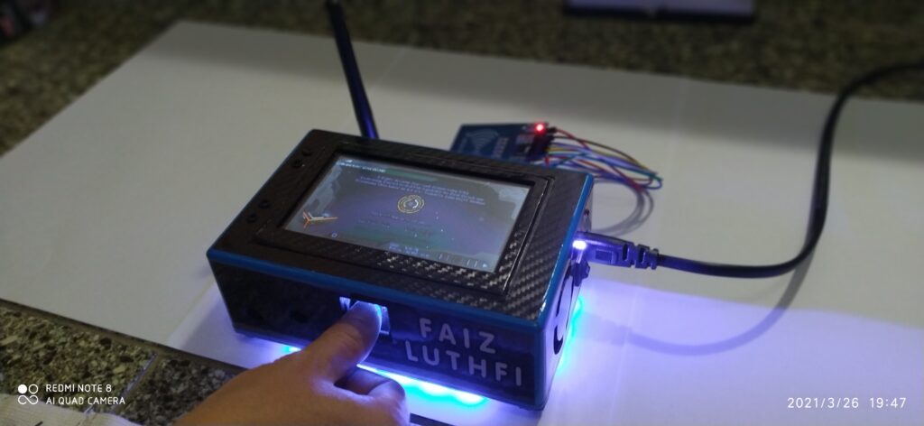
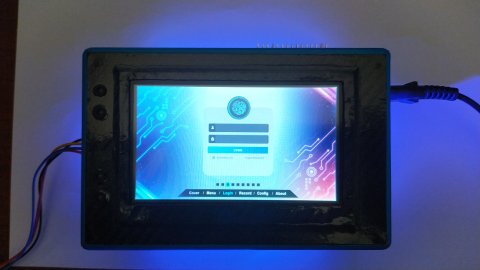
1. Dokumen
- Proposal
- Presentasi Proposal
- Design Drawing & 3D Model
2. Alat / Bahan
- Arduino IDE v.1.8.15
- Nextion Editor v1.63.3
- xampp PHP v8.0.8
- Solidworks 2020 SP2
- Fritzing
- NodeMCu ESP8266 Lolin v3
- HW-389 NodeMCU Shield for ESP8266 Lolin v3
- RFID module RC522 Kits S50 13.56Mhz
- Nextion HMI NX4827T043_11 4.3″
- Magnetic Door Lock 12v 180kg 300lbs
- Fingerprint Sensor
- TTP2238 Touch Sensor
- Box x5
- Resistor 330ohm SMD 1206
- LED 3mm + Bezzel
- DIP Switch 4pin
- Header Male 40pin
- Kabel Dupont Male to Male, Male to Female, Female to Female
- Cable Spiral
- Mini Rocker Switch
- USB to ESP8266 Serial Adapter Module Nextion
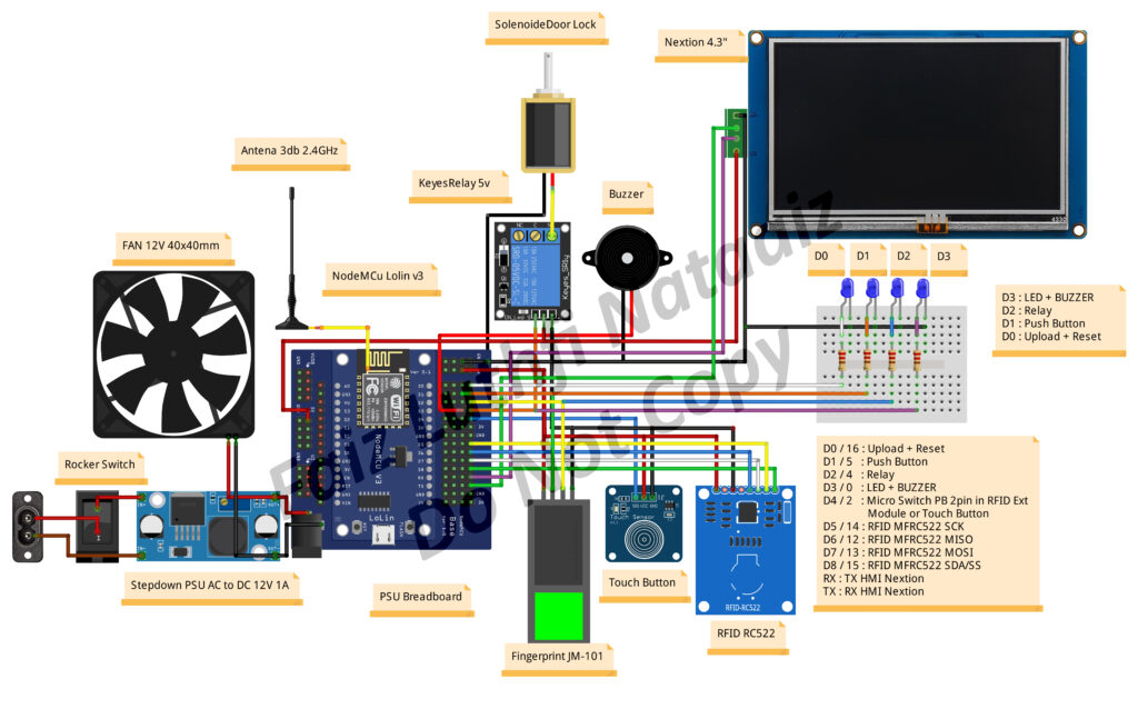
3. Skematik Rangkaian
1 2 3 4 5 6 7 8 9 10 11 12 13 14 15 16 17 18 19 20 21 22 23 24 25 26 27 28 29 30 31 32 33 34 35 36 37 38 39 40 41 42 43 44 45 46 47 48 49 50 51 52 53 54 55 56 57 58 59 60 61 62 63 64 65 66 67 68 69 70 71 72 73 74 75 76 77 78 79 80 81 82 83 84 85 86 87 88 89 90 91 92 93 94 95 96 97 98 99 100 101 102 103 104 105 106 107 108 109 110 111 112 113 114 115 116 117 118 119 120 121 122 123 124 125 126 127 128 129 130 131 132 133 134 135 136 137 138 139 140 141 142 143 144 145 146 147 148 149 150 151 152 153 154 155 156 157 158 159 160 161 162 163 164 165 166 167 168 169 170 171 172 173 174 175 176 177 178 179 180 181 182 183 184 185 186 187 188 189 190 191 192 193 194 195 196 197 198 199 200 201 202 203 204 205 206 207 208 209 210 211 212 213 214 215 216 217 218 219 220 221 222 223 224 225 226 227 228 229 230 231 232 233 234 235 236 237 238 239 240 241 242 243 244 245 246 247 248 249 250 251 252 253 254 255 256 257 258 259 260 261 262 263 264 265 266 267 268 269 270 271 272 273 274 275 276 277 278 279 280 281 282 283 284 285 286 287 288 289 290 291 292 293 294 295 296 297 298 299 300 301 302 303 304 305 306 307 308 309 310 311 312 313 314 315 316 317 318 319 320 321 322 323 324 325 326 327 328 329 330 331 332 333 334 335 336 337 338 339 340 341 342 343 344 345 346 347 348 349 350 351 352 353 354 355 356 357 358 359 360 361 362 363 364 365 366 367 368 369 370 371 372 373 374 375 376 377 378 379 380 381 382 383 384 385 386 387 388 389 390 391 392 393 394 395 396 397 398 399 400 401 402 403 404 405 406 407 408 409 410 411 412 413 414 415 416 417 418 419 420 421 422 423 424 425 426 427 428 429 430 431 432 433 434 435 436 437 438 439 440 441 442 443 444 445 446 447 448 449 450 451 452 453 454 455 456 457 458 459 460 461 462 463 464 465 466 467 468 469 470 471 472 473 474 475 476 477 478 479 480 481 482 483 484 485 486 487 488 489 490 491 492 493 494 495 496 497 498 499 500 501 502 503 504 505 506 507 508 509 510 511 512 513 514 515 516 517 518 519 520 521 522 523 524 525 526 527 528 529 530 531 532 533 534 535 536 537 538 539 540 541 542 543 544 545 546 547 548 549 550 551 552 553 554 555 556 557 558 559 | /* --------------------------------------------------------------------------------------------------------------- * # File Name : Access Control v3 * # TA Project : Faiz Luthfi Nataiz * # NIM : C1620201004 * # Judul TA : A Digital Security Door Lock System * with RFID: Enhancing Student Card * (KTM) Capability for Door Unlock and * attendance Class based on IoT using * NodeMCu 8266 * # Deskripsi : Perangkat elektronis yang digunakan untuk * absensi dan buka tutup pintu menggunakan * RFID dan fingerprint sensor. Dengan metode * MQTT dan OTA serta dapat diakses secara * localhost melalui penampil HMI touchscreen * panel (nextion 4.3 inch). * * Software Requirement * - Arduino IDE v1.8.10 * - nextion setup v1.62.1 * - xampp x63 v3.2.4 Compiled Jun 5th 2019 * - * # Hardware Requirement * - Input : RFID MFRC522 China Clone * - Output : Nextion 4.3" * - 3rd Platform : Google Firebase, Google Spreadsheet * - Methode : OTA and MQTT * - Aksesoris : 5pcs LED 5mm as Indicator & Buzzer * : Relay Module 1 Ch * : RTC and Micro SD Card * * # Feature alat : * 1. brightness (https://www.youtube.com/watch?v=AuFZNkD2osg) * 2. cek 4 led using hmi button (D0 ~ D8) * 3. showing network data (ip address and subnet mask) * 4. showing logbook record data RFID (absen hadir, pulang, istirahat/keluar) * 5. showing data * * # Editor : Budhi Prayoga,ST,.M.Eng * # Start Created : 09.04.2020 * # Last Update : 20.06.2021 | 18.06.2021 | 23.04.2021 * # Revisi : 4.0 * # Version : Beta * # Platform : * 1. Hardware : NodeMCu ESP8266 Lolin v3 * 2. Core Version : * 3. Development Env : Arduino IDE 1.8.10 * 4. Operating System : Win 7 x64 * # Library Version * 1. MFRC522 v1.4.4 * 2. ESP8266 v2.5.2 * 3. * # Setting in IDE * 1. Module : NodeMCu 1.0 (ESP-12E Module) * 2. Upload Speed : 115200 * 3. CPU Frequency : 80MHz * 4. Flash Size : 4M (No SPIFFS) * 5. Debug Port : Disable * 6. Debug Level : None * 7. lwIP Variant : v2 Lower Memory * 8. VTable : Flash * 9. Exception : Disable * 10.EraseFlash : Only Sketch * 11.SSL Support : All SSL Chipher (more compatible) * 12.Programmer : AVRISP mkII * * # Setting Preference in Arduino IDE * File -> Preferences (Ctrl+Comma) * 1. Show verbose output : Compilation (check) and upload (Check) * 2. Display Line Number (Check) * 3. Enable Code Folding (Check) * 4. Additionals Board Manager Url * https://dl.espressif.com/dl/package_esp32_index.json, http://arduino.esp8266.com/stable/package_esp8266com_index.json * 5. Directory Preferences * C:\Users\User\AppData\Local\Arduino15\preferences.txt * * # Location * 1. Arduino : C:\Users\User\AppData\Local\Arduino15\packages\arduino\hardware\avr\1.8.3\libraries * 2. ESP8266 : C:\Users\User\AppData\Local\Arduino15\packages\esp8266\hardware\esp8266 * --------------------------------------------------------------------------------------------------------------- * # Tutorial * > Watch Dog * 0. WDT Timer Test Code Sample * 1. Soft WDT Reset NodeMCu ESP8266 (google keyword : soft wdt reset esp8266 lolin) * https://community.blynk.cc/t/soft-wdt-reset/38353/4 Core v2.4.2 * https://github.com/miguelbalboa/rfid/issues/267 ESP SDK 2.1 or 2.2 / add a delay between SPI.begin() and init * 2. Theory (google keyword : watchdog esp8266 tutorial) * 3. Disable WDT * 4. Reset Causes Boot Mode List * > RFID * 1. What is RFID? How It Works? Interface RC522 RFID Module with Arduino * > Nextion * 1. Basic Program * 2. Youtube * NEXTION HMI DISPLAY WITH ARDUINO -Getting Started with LED ON/OFF * 3. Install USB to TTL * 4. Nextion TFT Touch Display Digital Clock v2.0 (Alarm Added) For NX4024K032_011 Nextion TFT * 5. Cara Print Out WiFi.localIP() di nextion * > SDK & Demos Espressif System * > Access Control Config via WEB * # Library * > MRFC522 1.4.4 : * > Nextion 4.3 : https://github.com/itead/ITEADLIB_Arduino_Nextion * Make sure you edit the NexConfig.h file on the * library folder to set the correct serial port for * the display. By default it's set to Serial1, which * most arduino boards don't have. * Change "#define nexSerial Serial1" to "#define nexSerial Serial" * # Catatan : * > Methode * 1. MQTT * 2. OTA * 3. xampp (web server apache dan database mysql * CSS bootstrap, jquery, java script * * > Arduino Debugging * > Nextion Upload Data * Baudrate : 115200 * Model : NX4827T043_011R(RTP) * Firmware : S151 * Device Serial Number : D26670B15B253137 * CPUID : 61488 * Flash Size : 16777216(16MB) * Address : 0 +-----------+ +-----------------------------------+ READ TAGS +-------------------------------------------+ | +--------------------+ | | | | | | +----v-----+ +-----v----+ | | |MASTER TAG| |OTHER TAGS| | | +--+-------+ ++-------------+ | | | | | | | +-----v---+ +----v----+ +----v------+ | | +------------+READ TAGS+---+ |KNOWN TAG| |UNKNOWN TAG| | | | +-+-------+ | +-----------+ +------------------+ | | | | | | | | | +----v-----+ +----v----+ +--v--------+ +-v----------+ +------v----+ | | |MASTER TAG| |KNOWN TAG| |UNKNOWN TAG| |GRANT ACCESS| |DENY ACCESS| | | +----------+ +---+-----+ +-----+-----+ +-----+------+ +-----+-----+ | | | | | | | | +----+ +----v------+ +--v---+ | +---------------> +-------+EXIT| |DELETE FROM| |ADD TO| | | +----+ | EEPROM | |EEPROM| | | +-----------+ +------+ +-------------------------------+ Use a Master Card which is act as Programmer then you can able to choose card holders who will granted access or not PIN |GPIO | Actual Pin | Status static const uint8_t D0 = 16; 1 > D10 TX x dipakai LED 0 Indicator Upload + Reset static const uint8_t D1 = 5; 2 > D4 + dipakai LED 1 Indicator Push Button when touched static const uint8_t D2 = 4; 3 > D9 RX x dipakai LED 2 Indicator Relay ON/OFF static const uint8_t D3 = 0; 4 > D2 dipakai LED 3 Indicator LED + BUZZER static const uint8_t D4 = 2; 5 > D1 belum terpakai static const uint8_t D5 = 14; 6 > x x tidak ada static const uint8_t D6 = 12; 7 > x x tidak ada static const uint8_t D7 = 13; 8 > x tidak ada static const uint8_t D8 = 15; 9 > S2 + belum terpakai static const uint8_t D9 RX = 3; 10 > S3 + belum terpakai static const uint8_t D10 TX = 1; 11 > x x tidak ada static const uint8_t S1 = MOSI 12 > D6 dipakai MFRC522 Biru SPI MISO static const uint8_t S2 = 9 13 > D7 + dipakai MFRC522 Putih SPI MOSI static const uint8_t S3 = 10 14 > D5 dipakai MFRC522 Kuning SPI SCK 15 > D8 + dipakai MFRC522 Hijau SPI SDA / SS Pin 16 > D0 + dipakai Buzzer Typical pin layout used: Source : https://github.com/miguelbalboa/rfid * --------------------------------------------------------------------------------------------------------------------- * MFRC522 NodeMCu Wemos D1 Mini Arduino Arduino Arduino Arduino Arduino * Reader/PCD ESP8266 ESP9266 Mega Nano v3 Leonardo Pro Micro Uno * Lolin v3 Uno 101 /Micro * Signal Pin Pin GPIO Pin Pin Pin Pin Pin * --------------------------------------------------------------------------------------------------------------------- * RST/Reset RST D3 9 5 D9 RESET/ICSP-5 RST * SPI SS SDA(SS) D8 (15) D8 10 53 D10 10 10 * SPI MOSI MOSI D7 (13) D7 11 / ICSP-4 51 D11 ICSP-4 16 * SPI MISO MISO D6 (12) D6 12 / ICSP-1 50 D12 ICSP-1 14 * SPI SCK SCK D5 (14) D5 13 / ICSP-3 52 D13 ICSP-3 15 * --------------------------------------------------------------------------------------------------------------------- *///inisialisasi pin RFID MFRC522#define SS_PIN 15 //D2#define RST_PIN 10 //S3#include "Nextion.h"//#include <Nextion.h> #include <SPI.h>#include <MFRC522.h>#include <ESP8266HTTPClient.h>#include <ESP8266WiFi.h>MFRC522 mfrc522(SS_PIN, RST_PIN); // Create MFRC522 instance.int statuss = 0;int out = 0;const int led0 = 16; //D0 GPIO16 Indicator Upload + Reset const int ledPB = 5; //D1 GPIO05 Indicator Push Button / Touch Button when pressedconst int relay = 4; //D2 GPIO04 Relayconst int buzzer = 0; //D3 GIPO 0 LED + Buzzerconst int btn = 2; //D4 Micro Switch Push Button 2 pin in RFID Ext Module//Network SSIDconst char* ssid = "Budhi_Prayoga";const char* password = "Yukihiro280588!";//const char* ssid = "LAB_TE";//const char* password = "innovation";//pengenal host (server) = IP Address komputer serverconst char* host = "192.168.100.20";//Declare your Nextion objects , pageid, component id., component name//Declare objects that we are going to read from the display. This includes buttons, sliders, text boxes, etc://Format: <type of object> <object name> = <type of object>(<page id>, <object id>, "<object name>");/* ***** Types of objects: * NexButton - Button * NexDSButton - Dual-state Button * NexHotspot - Hotspot, that is like an invisible button * NexCheckbox - Checkbox * NexRadio - "Radio" checkbox, that it's exactly like the checkbox but with a rounded shape * NexSlider - Slider * NexGauge - Gauge * NexProgressBar - Progress Bar * NexText - Text box * NexScrolltext - Scroll text box * NexNumber - Number box * NexVariable - Variable inside the nextion display * NexPage - Page touch event * NexGpio - To use the Expansion Board add-on for Enhanced Nextion displays * NexRtc - To use the real time clock for Enhanced Nextion displays * ***** *//* ID Halaman, ID Objek, Nama Objek * --------------------------------- * */// (page, id, "objname");NexButton b0 = NexButton(3,7,"b0");NexButton b1 = NexButton(3,8,"b1");NexText t0 = NexText(3,9,"t0");NexText t1 = NexText(3,12,"t1");NexNumber n0 = NexNumber(3, 11, "n0"); //ip addressString IPaddress;int counter = 1;int btnState = 0;//Register a button object to the touch event list//Format: &<object name>,NexTouch *nex_listen_list[] = { &b0, //button on &b1, //button off &n0, //number of ip address &t1, //text of ip address //void MIFARE(), NULL //String terminated};void setup(void) { Serial.begin(115200); SPI.begin(); // Initiate SPI bus mfrc522.PCD_Init(); // Initiate MFRC522 //Start inisialisasi koneksi WiFi WiFi.hostname("NodeMCU_Koko"); WiFi.begin(ssid, password); //cek koneksi wifi while(WiFi.status() != WL_CONNECTED) { //progress sedang mencari WiFi delay(500); Serial.print("."); } Serial.println(""); Serial.println("Wifi Connected"); Serial.print("IP Address : "); Serial.println(WiFi.localIP()); //end inisialisasi koneksi WiFi Serial.println("ready"); Serial.println("Initial Check LED Condition"); delay(150); // inisialisasi pin input pinMode(btn, INPUT); //D4 Micro Switch Push Button 2 pin in RFID Ext Module //inisialisasi pin output pinMode(led0,OUTPUT); //D0 GPIO16 Indicator Upload + Reset pinMode(ledPB,OUTPUT); //D1 GPIO05 Indicator Push Button / Touch Button when pressed pinMode(relay,OUTPUT); //D2 GPIO04 Relay pinMode(buzzer,OUTPUT); //D3 GIPO 0 LED + Buzzer // digitalWrite(led0,HIGH); digitalWrite(ledPB,HIGH); digitalWrite(relay,HIGH); digitalWrite(buzzer,HIGH); delay(2000); digitalWrite(led0,LOW); digitalWrite(ledPB,LOW); digitalWrite(relay,LOW); digitalWrite(buzzer,LOW); Serial.println("LED Check Finish"); delay(500); //nexInit(); //Register the pop event callback function of the components //b0.attachPop(b0PushCallback,&b0); //b1.attachPop(b1PushCallback,&b1); b0.attachPop(b0PopCallback,&b0); b1.attachPop(b1PopCallback,&b1); //n0.attachPop(n0PopCallback,&n0); //t1.attachPop(t1PopCallback,&t1); Serial.println("Dekatkan Kartu RFID Anda ke Reader"); Serial.println(); }void loop() { //nexLoop(nex_listen_list); // Check for any touch event //delay(150); //for stability //void MIFARE(); //Look for new cards btnState = digitalRead(btn); // check if the pushbutton is pressed. If it is, the buttonState is HIGH: if (btnState == LOW) { // turn LED on: Serial.println(""); Serial.println("HIGH"); digitalWrite(ledPB,HIGH); digitalWrite(relay,HIGH); digitalWrite(buzzer,HIGH); delay(150); } else { // turn LED off: digitalWrite(ledPB,LOW); digitalWrite(relay,LOW); digitalWrite(buzzer,LOW); delay(150); } int timeDelay = 10; while(timeDelay > 0) { if ( ! mfrc522.PICC_IsNewCardPresent()){ return; } // Select one of the cards if ( ! mfrc522.PICC_ReadCardSerial()){ return; } //Show UID on serial monitor Serial.println(); Serial.print(" UID tag :"); String content= ""; byte letter; for (byte i = 0; i < mfrc522.uid.size; i++){ Serial.print(mfrc522.uid.uidByte[i] < 0x10 ? " 0" : " "); Serial.print(mfrc522.uid.uidByte[i], HEX); content.concat(String(mfrc522.uid.uidByte[i] < 0x10 ? " 0" : " ")); content.concat(String(mfrc522.uid.uidByte[i], HEX)); } content.toUpperCase(); Serial.println(); if (content.substring(1) == "2D C7 E0 AF") //change UID of the card that you want to give access { Serial.println("t1.setText=" + String(mfrc522.uid.uidByte, HEX)); //t1.setText("UID Card: 2DC7E0AF"); Serial.println(""); Serial.println(" Access Granted "); digitalWrite(buzzer,HIGH); delay(500); digitalWrite(buzzer,LOW); Serial.println(); t1.setText("UID Card: 2DC7E0AF"); statuss = 1; //Serial.println("n0.val=2D C7 E0 AF"); //Serial.print("n0.val=" + String(counter)); //Serial.println("t1.txt=2D C7 E0 AF"); //t1.setText("UID Card: 2DC7E0AF"); //Serial.print("t0.txt=" + String(IPaddress)); //Serial.write(0xff); //Serial.write(0xff); //Serial.write(0xff); counter++; } else{ Serial.println(" Access Denied "); buzz(); } delay(150); } }void buzz(){ for (int a=0; a<6; a++) { digitalWrite(buzzer,HIGH); delay(50); digitalWrite(buzzer,LOW); delay(50); }}void MIFARE(){ //nexLoop(nex_listen_list); //Look for new cards /*if ( ! mfrc522.PICC_IsNewCardPresent()) { return; } // Select one of the cards if ( ! mfrc522.PICC_ReadCardSerial()) { return; } //Show UID on serial monitor Serial.println(); Serial.print(" UID tag :"); String content= ""; byte letter; for (byte i = 0; i < mfrc522.uid.size; i++) { Serial.print(mfrc522.uid.uidByte[i] < 0x10 ? " 0" : " "); Serial.print(mfrc522.uid.uidByte[i], HEX); content.concat(String(mfrc522.uid.uidByte[i] < 0x10 ? " 0" : " ")); content.concat(String(mfrc522.uid.uidByte[i], HEX)); } content.toUpperCase(); Serial.println(); if (content.substring(1) == "2D C7 E0 AF") //change UID of the card that you want to give access { Serial.println(" Access Granted "); digitalWrite(led3,HIGH); delay(1000); digitalWrite(led3,LOW); Serial.println(); statuss = 1; } else{ Serial.println(" Access Denied "); digitalWrite(led3,LOW); delay(1000); }*/}//Button b0 component popcallback function//When ON button is Released the LED turns ON and the state text changes//void b0PushCallback(void *ptr) // Press event for button b1/*void b0PushCallback(void *ptr) // push event for button b0{ //t0.setText ("Status: ON"); digitalWrite(led,HIGH); Serial.println("LED ON"); Serial.println("b0PushCallback");}void b1PushCallback(void *ptr) // push event for button b0{ //t0.setText ("Status: ON"); digitalWrite(led, LOW); Serial.println("LED OFF"); Serial.println("b1PushCallback");}*/void b0PopCallback(void *ptr){ // Release event for button b0 //t0.setText ("Status: ON"); digitalWrite(led0,HIGH); digitalWrite(ledPB,HIGH); digitalWrite(relay,HIGH); digitalWrite(buzzer,HIGH); Serial.println("LED ON"); Serial.println("b0PopCallback");}//Button b1 component popcallback function// When OFF button is released the LED turns OFF and the state text changesvoid b1PopCallback(void *ptr){ // Release event for button b1 //void b1PushCallback(void *ptr) // Release event for button b1 //t0.setText ("Status: OFF"); digitalWrite(led0,LOW); digitalWrite(ledPB,LOW); digitalWrite(relay,LOW); digitalWrite(buzzer,LOW); Serial.println("LED OFF"); Serial.println("b1PopCallback");}/*void n0PopCallback(void *ptr){ //IPaddress = WiFi.localIP().toString(); //n0.setValue(WiFi.localIP()); //Serial.println("n0.val=" + String(IPaddress)); //dbSerialPrintln("n0PopCallback"); //n0.setValue(50); //Serial.print("n0.val=2D C7 E0 AF"); //Serial.print("t1.txt=2D C7 E0 AF"); //Serial.write(0xff); //Serial.write(0xff); //Serial.write(0xff);}void t1PopCallback(void *ptr){ //Serial.print("n0.val=2D C7 E0 AF"); //Serial.print("t1.txt=2D C7 E0 AF"); //Serial.write(0xff); //Serial.write(0xff); //Serial.write(0xff); //t1.setText(WiFi.localIP()); //Serial.println("t1.setText=" + String(IPaddress)); //dbSerialPrintln("n0PopCallback"); //n0.setValue(50);}*/ |
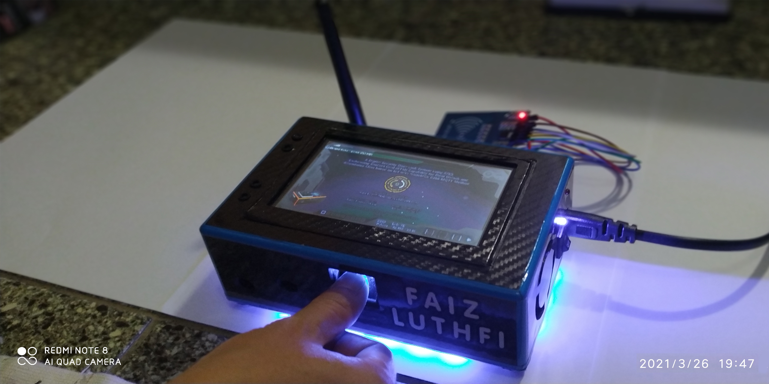
4. Galeri
5. Video Demo


 Visit Today : 22
 Visit Yesterday : 60
 This Month : 258
 This Year : 258
 Total Visit : 42067
 Hits Today : 22
 Total Hits : 36319
 Who's Online : 1